E0451-521-051 by Okuma
Get a Quote for E0451-521-051
Request a quote or call us now at 1-888-551-3082!
We respect your privacy. Your information is safe and will never be shared.
Secure Online
Checkout
Free Ground
Shipping
One Year
Warranty
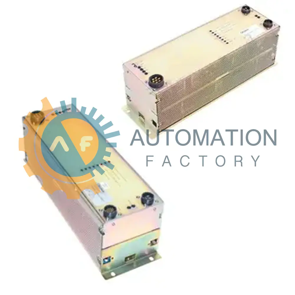
The E0451-521-051 power board is produced by Okuma within the E0451 Power Supply Boards series. Serving as the CPU power supply in an Okuma CNC control, it converts the cabinet's AC input into regulated DC rails that power the processor rack and peripheral logic. By stabilizing multiple low-voltage rails and coordinating power sequencing, the board maintains proper microprocessor reset timing and helps prevent data corruption during startup or shutdown events in industrial automation. Its regulated outputs support the reliable operation of memory devices, control electronics, and other components connected through the processor backplane.
The input side of the board accepts 220 VAC from a single-phase feed, so no line-to-line balancing is required inside the control enclosure. The internal feedback loop maintains the 5 V rail at 5.1 VDC, which is the factory-set logic voltage delivered to CPU and memory devices. An undervoltage monitor trips at 4.6 VDC and sends an alarm signal to the control if regulation falls outside the safe tolerance. Voltage trimming is limited to the +5 V rail only, allowing that output to be adjusted without affecting the auxiliary outputs. Check terminals for 0 V and +5 V provide accessible points for multimeter measurements during preventive maintenance.
The secondary section supplies three logic rails consisting of +5 VDC, +12 VDC, and +24 VDC. These outputs power I/O converters, encoder readers, and relay coils connected to the processor backplane. A separate machine-safety circuit supervises the isolation rail, and its monitor line remains at +24 VDC while the external source is available. The isolation circuit uses an external 120 VAC-to-24 VDC supply, keeping this source separate from the board's main conversion stages. Two Iso UV disable pins allow the isolation undervoltage monitor to be bypassed when service work requires that function. The board installs in the CPU rack and follows a sequence in which the CPU powers on first and turns off last, helping prevent bus transients from reaching logic modules before they are initialized.
Technical Specifications
5 V Factory Setpoint
5.1 VDC
5 V Uv Alarm Trip
4.6 VDC
Adjustable Output
+5 V Only
Check Terminals
0V, +5V
Component Type
CPU Power Supply
Dc Outputs
+5 VDC, +12 VDC, +24 VDC
Input Phase
Single-Phase
Input Voltage
220 VAC
Iso Monitor Voltage
+24 VDC
Iso Source
External 120VAC-to-24VDC
Iso Uv Disable Pins
2
Mounting Location
CPU Rack
On-off Sequencing
CPU First On, Last Off
Contact Us
1620 Old Apex Road, Cary, NC 27513, USA
Toll Free: 1-888-551-3082
International: 1-919-443-0207
Fax: 1-919-867-6204
Email: sales@wakeindustrial.com
Shipping Options




Payment Methods




Need Assistance?
Our team is here to help you find the right part for your needs.


